Showing posts with label Echo Effect. Show all posts

Tuesday, 21 May 2019

Ping Pong Delay - Re-imagined differently! (Plus M4L Audio switches)

My first AUDpiPOde (Ping Pong Delay) M4L device had some protracted problems, and hopefully the additional tweaks for version 0.04 should fix them. But in the course of learning more about how the original (and soon to be deprecated) Ableton Live Ping Pong Delay actually worked, I realised that I had re-imagined it along the wrong vector, and that my 'all stereo' approach had too many differences to the original. The band-pass filter also proved to be a significant challenge, and dropping it again restricted the flexibility. (...Now, I'm not the greatest fan of 'muddy' echoes, but they are a defining characteristic of some vintage tape echo units...)


So, here's almost the opposite of AUDpiPOde - it uses a tapped delay line, mixes the channels into a mono signal for the echoes, and puts back the 'far-from-perfect' band-pass filter emulation made up from a high-pass and low-pass filter (and I need to learn more about filters in Max!). It uses a different 'freeze' method (as well as the ones I added), and it provides a 'Thru' button to bypass the filters. I also tweaked the delay routing so that you can have 'Echo in the Left channel first, then the Right channel' or 'Right channel first, then the Left channel' - which is quite striking if you are used to the 'feel' of the original!

And the name? AUDpiPOde-A, of course!

Making audio switches

One of the traps for people who are trying to learn Max are the large variety of switches. There are simple switches, complex matrix switches, routers and the names are sometimes different if audio is being switched. I'm still gathering information for a guide, but in the meantime, here's what I've been doing to build custom audio switches...

LR 'Left first' 'crossover' toggle switch

The 'Echo in the Left channel first, then the Right channel' or 'Right channel first, then the Left channel' switch functionality is a good example. All that needs to happen is that the two outputs from the delay (the middle tap and the end) need to be routed to the Left and Right channels, in the two possible combinations.


This is the output stages of the AUDdiPOde 'Ping Pong Delay' device, with, from top downwards, the feedback rotary control, the 'LR' echo order control, and the Dry/Wet rotary control. For the Feedback control, you can see how the line~ object is fed with pairs of '<new value> 50ms' values for each new line segment, so that the multiplier that does the feedback only gets values that change reliably slowly (each new value takes 50ms to happen) and so the amplitude of the feedback signal doesn't jump suddenly.

Just below the feedback code, the 'LR' box is where the interesting switching takes place. The 'p cross_mr' object has two stereo inputs (from the tap and the final output of the tapped delay line) and two stereo outputs (which go to the Dry/Wet' balance control library object. The 'LR' toggle switch controls the 'p cross_mr' object, and all it does is change between the default 'Left In to Left Out, Right In to Right Out' switch setting to the alternate 'Left In to Right Out, Right In to Left Out' which reverses the channel ordering. So in the default 'Left first' position, the 'LR' switch controls the 'p cross_mr' object so that the tap output of the delay line goes to the Left In of the 'cross' switch and comes out of the Left Out, which means that the tap output is heard in the Left channel first, whilst the final output of the delay is routed to the Right channel and so is heard later. When the 'LR' toggle is in the 'Right first' position, then the 'cross' switch routes the tap output of the delay to the Right channel where it is heard first, and the final delay output is routed to the Left channel, where it is heard later. So the 'cross' switch connections are either straight-through, or crossed-over - hence the name.

I don't think there is a standard MaxForLive switch that does this 'out of the box', so I made the 'cross' switch:

  
There are only two objects used inside the 'cross' switch - gate~ objects, which are just on/off switches for audio signals, and one of those arcane 'not quite obvious' special-purpose modifier objects: '!- 1', which inverts a 0 or 1 control value. So 0 becomes 1, and 1 becomes 0 - it is an 'inverter' for  control values. If you replace the two left-hand gates with through connections (closed switches) then you can see that A goes to X, and B goes to Y. Whereas if you replace the two right-hand gates with throughs then A goes to Y and B goes to X, and so achieves the straight-through or
crossover switching.


In physical hardware, then crossover switches like this are very easy to spot when you look at the rear  wiring of a front panel - the inputs go to the centre common part of the switch, whilst the outputs come from one of the outer pairs, and two wires cross over the outer pairs - so you can see at a glance that it is a crossover switch!

Fade switches

If you just switch from one audio signal to another, then you get sudden changes in the value of the signal, and these can cause clicks in the audio. To avoid this happening, one technique is to 'dip' the audio volume as you do the switching, and then restore it afterwards. This approach is used in AUDpiPOdePLUS, the 'performance-oriented' freeze echo device.

For this technique to work, then a sequence of operations need to happen in the right order, and at the right times. Here's the sequence:

1. The volume is at maximum.
2. trigger for the switching occurs. In the AUDpiPOdePLUS device, this happens when one of the 'Freeze' mode buttons is clicked.
3. The volume starts the fade downwards to zero.
4. The volume stays at zero for a few milliseconds, whilst the switching takes place.
5. The volume starts to fade back up.
6. The volume reaches maximum level again.

Once again, there wasn't a standard pre-prepped switch for the 'Freeze' mode button signal routing, so I made my own. It uses the 'constant volume' technique from a previous blog post, plus the 'gate~' switching describes earlier, with added 'fading' to dip the audio signals in and out at the right moments.


The three 'Freeze' modes are A, A+B, and B, which correspond to 'Tap', 'Final output', and 'Tap and Final output' being fed back to the input of the delay. the volume compensation is done using a 1/n multiplier, so that the final multipliers multiply by 1 for single inputs, or by half for two inputs. The fading is done by the 'p dip_mr' objects, whilst the gate~ objects do the switching, and the 'pipe' objects just delay th switching so that it happens when the volume is zero. But the really interesting stuff is in the 'dip' object:


Unfortunately, once you have seen it, then it isn't quite a magical as you might have expected. The line falls to zero in 50 milliseconds (ms), then stays there for 10 ms, then rises back to 1 in 50 ms again. The 0to 1 values of this 'fat' or 'dip' envelope are the multiplier value used in the multipliers, so there's no complicated conversions required. Here's the same thing expressed as a timing diagram:


So the trigger happens when one of the 'Freeze' buttons is clicked. The fade envelope starts to fall, and when it reaches zero, then the multiplier is zero, which means that no audio gets through the multiplier. The switch control has been delayed from when the trigger happened, and the audio signal is switched whilst the envelope is at zero and there is no audio signal getting through. Once the switching has happened, then the fade envelope returns back to 1, and the audio has been switched without any click happening.

This 'dip' fade envelope technique can be used whenever you want to switch from one audio signal to another without having a click. There are other ways to do it, including some that don't have any 'dip' in the audio, but this is a simple starting point for further explorations.

Filtering

I have struggled with the filtering all the way through the two 'AUDpiPOde' devices. In this 'A' version, I have revised the filtering again, so there is now only a single low-pass filter instead of two in cascade, and the high-pass filter is now a State Variable design because the 'subtracted low-pass' technique didn't seem to work very well (but then inside a feedback loop is always a bad place for any filter!). This is far from a perfect design, and full credit to the Ableton coders who have a far superior filter in the original Ping Pong Delay, and in the new 10.1 Delay devices. If only such a filter was available in MaxForLive...

Getting  AUDpiPOde-A 0v05

You can download AUDpiPOde-A 0v0for free from MaxForLive.com.

Here are the instructions for what to do with the .amxd file that you download from MaxforLive.com:

     https://synthesizerwriter.blogspot.co.uk/2017/12/where-do-i-put-downloaded-amxd.html

(In Live 10, you can also just double-click on the .amxd file, but this puts the device in the same folder as all of the factory devices...)

Oh, yes, and sometimes last-minute fixes do get added, which is why sometimes the blog post is behind the version number of MaxForLive.com...

Version 0.05 gives some idea of the development problems that I have had with these 'ping pong delay' devices! It seems that having ping pong delay plus several freeze modes is a good way to get confused about single routing, and I have made more mistakes than I want to think about. So my normal 'Work In Progress' label definitely applies to this device!

Modular Equivalents

In terms of basic modular equivalents, then AUDpiPOde-A would require two band-pass filters, two delays, some utility switches, and two mixers, giving a total of about 5 ME.


Sunday, 12 May 2019

Frozen Echoes - a sneak peak inside my M4L development pipeline...

I'm going to break my usual routine this time. Instead of a finished MaxForLive device, I'm posting an early prototype so that you get to see something before I have smoothed any rough edges.

For a long time, I've been fascinated by syncopation, and so the '3' and '5' buttons in Ableton Live's Ping Pong Delay have always been my defaults. Whilst working on my re-inagining of that device, I realised that the extended 'Freeze' buttons that I had added could also be pushed further - into territory that my AUDhexECHO partly covers, but with a different, more rhythmic, more performance-oriented slant. The result is a 'Plus' version of AUDpiPOde, but there's a lot of extras in that 'Plus'! (I also removed the input filtering, but I think the additions make up for that!)

AUDpiPOdePLUS

Here's the basic device: AUDpiPOde split into two separate channels, and without the common time and feedback controls - so just an echo effect.


The left half of each to the channel panels is just taken from AUDpiPOde, and in this mode, you get two different delay times for each channel, so the ping-pong echoes just bounce back and forth in stereo, as you would expect - but because the time delays are different, the timing is more... interesting.

The two buttons marked 'Free' mean that the two channels are separate. If you click on the one above the 'ms' time setting in the Right channel then it changes to 'Anti', which indicates that the two time delays work in opposition. So the time delay for one channel goes up as the other channel goes down.


So 1750 ms in the Left channel equates to 2250 ms in the Right channel, and notice that the time delay adjuster is greyed out in the Right channel - using the 'Anti' button just makes syncopated echoes easier to set up for 120 ppm (at the moment), but it is a good starting point for the next stage.

The panel on the far right contains common controls, including 7 'performance' controls. The largest three are just common versions of the three 'Freeze' buttons: Freeze (Ping), Freeze (Ping and Pong) and Freeze (Pong), where 'Ping' is a 'same channel' echo, and 'Pong' is an 'other channel' echo. The Dry/Wet rotary control controls the mix between the straight-through audio and the processed audio, and the 'MakeUp' slider/indicator is only active when 'freezing' is happening. The final four buttons are connected to the 'freeze' loop processing...

The right half of each of the channel panels contains two processors: a limiter; and a frequency shifter. These two audio processing effects are not inside the feedback loop that is associated with the 'Feedback' rotary control. Instead they are inside what I will call the 'freeze' loop - because this echo effect breaks two of the 'rules' that people often apply to echo units:

1. 100% feedback will cause the delay to oscillate, which is generally considered to be bad.
2. Don't put any audio processing in the feedback loop, because it will affect the feedback and might cause it to exceed 100%, in which case the first rule applies.

Luckily, inside the 'freeze' loop, things are slightly different, and this design has 100% feedback plus audio processing, and it is much harder to get it to oscillate than you might expect. In fact, the freeze loop is specifically designed to avoid the usual runaway feedback, although nothing is perfect! When the 'freeze' mode is selected, the input is switched from the audio input to the output of the freeze loop processing, so the delay is looped around itself, and only outputs audio signals. The Dry/Wet balance control shifts the all 'Wet' when 'freeze' mode is active, so that only the frozen audio is output.

One of the major changes between the plain and the 'Plus' versions of AUDpiPOde is hidden away in the Max code, and it is the audio switching. The Plus version fades in and out smoothly between audio signals, whereas the plain version just switches immediately. The freeze mode only works when the transitions in and out are as smooth as possible, and the fades help to minimise them. This design does to use cross-fades - I'm still trying to get my head around a way to do this, and it remains one of those 'one day I will figure it out' aspects of my programming.

And so to 'freeze' mode:


The selected button is 'P' , which is 'Freeze Pong', so the output goes round each delay in series, and with the 'Anti' time delay setting, this means that the audio will be delayed by 1000 ms, then 3000 ms, the 1000 ms, etc. The frozen output is thus 4 seconds (4000 ms) long in total, and so it repeats every 4 seconds. And because it is frozen, it can repeat indefinitely - although if you activate the Limiter or Frequency Shifters then this isn't true! (because they alter the audio) And when you want to stop the repeats of the frozen echoes, then you just click the 'P' button again and the Dry/Wet control will return to the previous setting, smoothly restoring the echo effect as before the freeze was activated.

So the performance process goes like this:
1. Set up the echo timings in 'Anti', so that the echoes stay in sync (or alternatively, you could just abandon sync!)
2. Click on one of the three 'Freeze' buttons.
3. Let the frozen echoes repeat...
4. Click on the highlighted 'Freeze' button to return to echo mode.

Things to fix

There's quite a lot of extra text needed here to describe the operation of the Limiter and Frequency Shifter effects. The timings in the time delay selection tabs aren't in the right order! I need to fix this. Also, there's that cross-fade that has so far defeated me! (Which means that the frozen echo loop is not quite perfect...) Finally, I'm wondering if I should put filtering inside the 'freeze' loop, which might be quite interesting...

Anyway. Enjoy!

Getting AUDpiPOdePLUS 0v03

You can download AUDpiPOdePLUS 0v03 for free from MaxForLive.com.

Here are the instructions for what to do with the .amxd file that you download from MaxforLive.com:

     https://synthesizerwriter.blogspot.co.uk/2017/12/where-do-i-put-downloaded-amxd.html

(In Live 10, you can also just double-click on the .amxd file, but this puts the device in the same folder as all of the factory devices...)

Oh, yes, and sometimes last-minute fixes do get added, which is why sometimes the blog post is behind the version number of MaxForLive.com...

Modular Equivalents

In terms of basic modular equivalents, then AUDpiPOdePLUS would require two delays, two limiters, two frequency shifters, some utility switches, and two mixers, giving a total of about 9 ME.


Thursday, 9 May 2019

Ping Pong Delay re-imagined for Live 10.1 in M4L...

I'm sure that we are about to be swamped by lots of 'homage', 'retro' and 'for compatibility' versions of the classic Ableton Live 'Ping Pong Delay' plug-in effect so that anyone who likes the simple 'about to be deprecated' effect can continue to use it. But rather than just recreate it, why not take the opportunity to re-imagine it, and try to produce something that reflects what it would be like it it was a brand new device made today? Well, I took the re-imagination route, and as usual, the story isn't completely straight-forward...

Let's start with the classic 'Ping Pong Delay' audio effect:


With the input filtering at the top, then the quick 16th note delay time selector buttons, then the Sync, Freeze and 'Adjust' boxes, and finally the Feedback and Dry/Wet rotary controls, it manages to squash a lot into a small space. I've clicked on the '3' and '5' buttons and used the '% tweak' Adjust box more times than I care to think about, and that tiny little 'F' Freeze button is often overlooked as a creative performance tool... (and not to mention the often overlooked 'Control (M)/Right (W)-Click' in the name bar to reveal the 'hidden' context menu with 'Repitch, Fade and Jump' modes - and probably a standard Ableton question to people who think they know Live...)

Ableton Live 10.1 includes the new version that combines Simple Delay and Ping Pong Delay not one device:


(screenshot from live-101-user-wavetables-new-devices-and-workflow-upgrades  https://www.ableton.com/en/blog/live-101-user-wavetables-new-devices-and-workflow-upgrades/ )

There's a lot of interesting additions in the new version: separate delay time buttons for each stereo channel, plus %tweaks, the filter is now 'bypass'able, and the 'F' Freeze button is now made lots more obvious by being labelled as 'Infinite feedback', which I'm sure is going to attract lots more explorative clicks!  All-in-all, it looks cool, and I'm looking forward to it.

Before re-imagining

Back to the classic Ping Pong Delay... What would a modern 'revisited' version include? How about note value based time buttons? How about freezing based on separate stereo channels instead of just the mixed output? How about a 'bypass' for the filters?

First off, I need to look at the structure of just about all of the stereo delay devices that I have programmed in MaxForLive. My preference has always been for stereo in and stereo out, probably because I was raised in an era when not everything that was 'stereo' was actually stereo (and with two flavours of quadraphonic sound fighting it out when I first started reading electronics magazines), and so there's a bit of a common theme (and there's a partial collection from way back in history here, if you are interested...):


This is definitely a 'stereo in, stereo out' delay/echo device, and I have shown only what I tend to call 'Cross feedback', which is feedback that goes to the other channel. So, if you imagine a drum sound on just the left channel input, then assuming that the Dry/Wet mix control is set mid-way and there is some feedback, the output will be the drum sound from the left channel, then the delayed drum sound from the left channel, then the delayed drum sound (double-delayed) from the right channel, then the triple-delayed drum sound from the left channel, followed by the quadruple-delayed drum sound from the right channel, and so on. Each new delayed drum sound bounces back and forth from left to right, and if there's another bit of audio in the right channel, then that will be output (delayed) from the right channel first, then the left, and so on.

I have to say that I'm tempted to go back into some of my older devices and tweak them so that the 'first delay output channel' is selectable. Now that I have been working on ping-pong delays, I'm wondering if being able to decide if a drum that starts on the left should have the first echo from the right, not the left as shown here... It might be interesting to revise those old devices...

Anyway, if you have been following my recent devices you might be thinking that the 'basic' delay shown above is simplified from what I'm currently doing, and you would be right. Here's a more representative delay device - reminiscent of parts of the recent 'hex' series:


In this example, there are two feedback loops: one for the same channel, and one ('cross') for the other channel, which lets you decide if you want the repeat echoes to be in the same stereo channel or to bounce back and forth between the two channels with each successive repeat. The output panning is also controlled by an LFO driving a panner, so the actual stereo field can be animated as well.

What I hadn't done in any depth when I first started was examine the original Ableton Live 'Ping Pong Delay' device. If you are going to 're-imagine' something, then knowing too much about it is going to affect what you do and restrict your creativity, so I just took my usual delay and gave it a UI skin that was strongly influenced by the original device. It turns out that the Ableton device is rather different...


Let's go back to that drum sound on the left channel input - there's a screenshot of the text setup above - I just set the drum sound on the left or right channels using the Utility device, and then used the Dry/Wet mix rotary controls to look at the input and output of the two devices. You need to make sure that you only enable one device at a time, otherwise all those echoes can be very confusing!


If you send the 'left channel' drum sound to the original Ableton Live 'Ping Pong Delay' device, then you get the dry signal first in the left channel, then the delayed version in the left channel,


then a double-delayed version in the right channel, and so on. So far, it behaves just like mine.


But if you then try a drum sound in the right channel input, then you get the delayed version from the left channel first, then the double-elated version from the right channel, and now it is behaving VERY differently from my version.


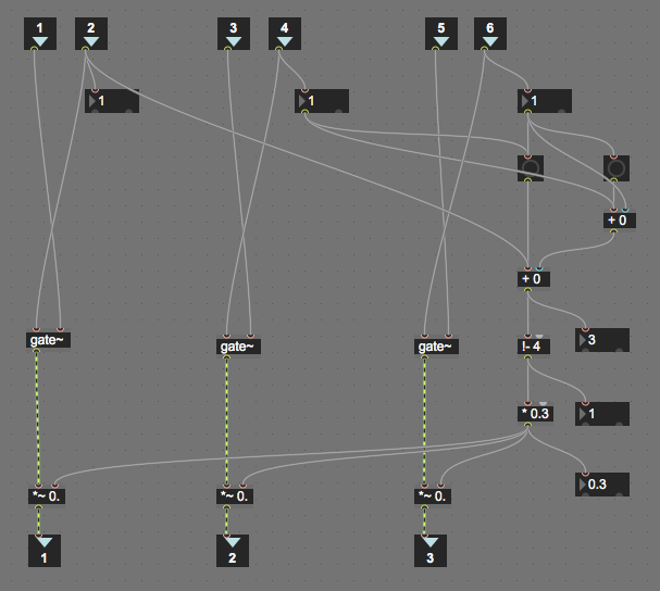
So, based on this, it seems like the original Ableton 'Ping Pong Delay' device internal structure looks like this:


So the left and right channels are mixed together into a 'mono' single,and this is then delayed and output to the left channel, then that is delayed and output to the right channel, and the feedback goes round both delays. This is why a drum sound on the right channel appears at the left output for the first echo, then the right channel for the second echo, and so on, back and forth between the two channels. Note that with this structure, the first and second echoes are at the same volume in the left and right channels, whereas in my echo devices, the volume of the second echo depends on the 'Feedback' rotary control.

So now I knew the difference between the Ableton device and mine!

Frozen echoes

Let's look at freezing the echo, where the output of the delay is connected directly and solely to the input. Here's what it looks like for the Ableton device:


As you can see, the output will just 'ping-pong' back and forth between the left and right channels with each subsequent echo.

For my device, then there are several ways to do the freezing, and here's one of them:


This behaves in exactly the same way as the Ableton one: the output bounces back and forth from left to right with each successive echo. I have not included the Dry/Wet mix in this diagram because it was originally drawn for the AUDpiPOdePLUS device, where the Dry/Wet mix is inactive when the echoes are frozen.

Anyway, the end result of all of this investigation and looking at how echo devices work is two MaxForLive devices:

1. AUDpiPOde - the first Ping-Pong Delay device that appeared on MaxForLive.com, and which uses my preferred stereo delay to give stereo echoes that bounce back and forth between the left and right channels. This is not a faithful emulation of the original Ableton 'Ping Pong Delay' device - and so the word: 're-imagining' is very apt - this is how I would program a Ping Pong Delay device now.

2. AUDpiPOde_A - which is the second Ping-Pong Delay device that I will post on MaxForLive, and this uses a single tapped delay to give a different ping-pong effect - where the signal that bounces is a mix of both input channels. This is a closer emulation of the original Ableton Ping Pong Delay device in pre 10.1 Ableton Live.

This gives you both double value (which is her to measure for devices that are free!) and a choice: you can have 're-imagined' or 'close'. I hope that you find both variants useful, and don't forget that all of the re-imagining also produced another device: AUDpiPOdePLUS, which (despite the name) is actually a performance-oriented delay device which extends the 'frozen echo' feature into something rather different.

Re-imagining

Anyway, on with the re-imagined delay device:

Here is AUDpiPOde (from the first two characters of ping, pong and delay). I worked on the note value time delay buttons first. I replaced the 1,2,3,4,5... with note values, using the internal M4L time notation: 16d, 16, 16t for dotted 16th, 16th and 16th triplet, etc. I also added more buttons, from 128th note to 1 note (15.62 ms to 2000 ms at 120 bpm).

I also used the '% tweak' Adjust box to automatically switch between 'Sync' and 'Not in Sync'. So when you click a note value button then the delays are in sync, but if you use the '% tweak' Adjust box (with the triangle) then the time delays are not in sync with Live's timing.

Trying to keep the buttons as large as possible, whilst still keeping a small but neat rectangle of buttons meant that the obvious 'three values' of dotted, note and triplet organisation was awkward, and so I opted for a more free-form set where 2, 4, 8 and 16 are on a diagonal, and 32 and 64 have their own tiny diagonal. It isn't perfect, but it keeps the button grid small and neat.


For the freezing, then I added two extra buttons. The 'F' button is as before, and loops the output of the delay back to the input, thus giving the infinite delay that the new 10.1 makes much more explicit. Note that when the delay is frozen, then the feedback rotary control has no effect.


The new 'P' button loops around the stereo channel reversed audio signal, so if the input is just in the left hand channel, then the first delayed repeat will be in the right hand channel, then the second delayed repeat will be in the left hand channel again. being able to ping-pong in a frozen loop is very cool!


The final freeze button is labelled 'P+F' and combines the two previous buttons into one. For this delay, where both channels have the same delay time, then it makes no difference, but if this was available in the 10.1 delay, where each channel can have different delay times, then some very interesting results would be available. Now although you can do exactly the same effect in my AUDhexECHO effect with appropriate settings of the controls, this seemed like something for a 'Plus' version of this effect, and so expect exactly that very soon!


The filters were a challenge. Max For Live provides a lot of filters, and some very sophisticated tools to help you design specific special-purpose filters, but there are two problems. Firstly, the Ping Pong Delay filter is a band-pass filter - the two controls that are provided are the centre frequency and the bandwidth. But for a wide bandwidth, then a combination of a high-pass and a low-pass is easier to make, but then the controls are more complicated - you need to send the centre frequency to both filters, and then add or subtract half of the bandwidth setting. To complicate things even more, the frequency axis is logarithmic, where the frequency goes up by 10 times for each 'decade' block as you move across from left to right (you can see this in the spacing of the lines in each 'decade' block).


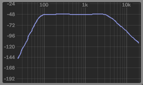
In the filter response plot for a band-pass filter shown above, the major lines at the end of each 'decade' block are 100 Hz, 1 kHz, an 10kHz - so the final vertical line on the right hand side is 20kHz, and zero Hertz is way off the the left somewhere. So the band-pass filter shown has a pass-band between just under 100 Hz to just over 3kHz.

The display in Ping Pong Delay is much smaller, of course:


But notice that each of the decade blocks have the same pattern as the first plot, where the vertical lines get closer and closer together as the frequency goes up, and (by implication) the far right edge is 20 kHz. The yellow dot is kind of centred on 1 kHz, and the centre frequency is 949 Hz, with a Q or resonance of 6.17 (which controls the bandwidth of the filter). Now, having the centre of the display at 1 kHz may not be what  you expected, but look at the right hand side - the narrow vertical strip from 10 kHz to 20 kHz is the same frequency range as the whole of the left hand side of the graph, from the 10 kHz vertical line leftwards.

So if we are going to use a simple x/y controller object from Max to control a band-pass filter, with centre frequency on the horizontal axis, then a pictslider output goes from 0 to 127 horizontally. If 0 represents 0 Hz, and 127 represents 20 kHz, then 1 kHz is going to be a value of about 63 or so, and 10 kHz is going to be at about 110 or so. To convert a linear controller value into a logarithmic value requires that we use an exponentiation function: using the 'pow' object in Max. Using the 'pow' object can be quite tricky, because small changes of input values can have large effects on the outputs. My usual technique is to transform the 'pow' into a 'domain' where figuring out what is happening is easier, and then to transform back once the settings are known. Here are two examples which illustrate this:


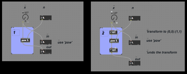
Box 1 shows a simple way to use 'pow', whilst Box 2 shows the 'transform' method. At first sight, Box 2 seems to add complexity, so we need to look at the inputs and outputs of the two boxes.

Box 1 first:


When n = 0.5, the output only goes to 11, and so the integer 'multislider' object that I'm using to do the plots quantises the outputs, but you can see that the curve goes from 0,0 to 127,11 and is gradually tailing off (just imagine a smooth curve!). When n=1, then the output is a straight diagonal line from 0,0 to 127,127.


When n=1.5 then the curve looks like a classic exponential, and goes up to 127,1431. When n=2 ('y=x squared' is how you would say it) then the max is 127,16129 (127 squared, of course).


  For n=2.5, then the rightist point is 127,181754, and for n cubed (n=3), then it is 127, 2048383.

In order to use these curves, then you would need to scale the maximum output, but this changes for each value of n:

n       maximum output
0.5             11
1.0           127
1.5         1431
2.0       16129
2.5     181754
3.0   2048383

You can auto scale by dividing by 127 to the power n, but this means that we are doing two 'pow' operations every time, which seems inefficient.

Alternatively, the 'transform' method adds scaling (divide by 127) around the 'pow' function so that it always has inputs between 0,0 and 1,1, and then multiply it by 127 to get the same output as the original UI object. The graphs now look like this:


The 'pow' object is now getting floating point inputs, and so we can see what the actual curve looks like without the accidental quantisation! Notice that each curve goes from 0,0 to 127,127.


And again for n=1.5 and n=2, the output is from 0,0 to 127,127.


And finally, exactly the same output range again!

Putting a transformed 'pow' object inside my filter testing gave this max patch:


This time, Box 1 contains a transformed pow function (I was testing out n=3 in this screenshot), and Box 2 contains the max objects to try and turn the horizontal movement in the pictslider into the correct centre frequency for the band-pass filter, and for vertical movement in the pictslider to control the Q, resonance or bandwidth of the filter - which I implemented as a plain butterworth type. Unfortunately, I couldn't get the mouse interface with the pictslider to feel anything like the Ping Pong Delay original, and having a 'difficult to use' filter section in a re-imagining f a classic Ableton Live device seemed like a bad move. So I reverted to two simple filters instead:


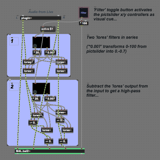
So, in this version, there are two pictsliders: one for the high-pass filter, and one for the low-pass filter. in both of them, horizontal movement controls the centre frequency, whilst vertical movement controls the Q, resonance or bandwidth of the band-pass filter. This simplicity felt much better than the previous complexity, and this is what is implemented in the current device.

Note that the high-pass filters are made from low-pass filters by subtracting the original input from the low-pass filter output. This turns a 'lores' object into a kind of 'hires' object. (although there isn't a 'hires' object in Max, of course!)

The filters can be bypassed by using the Filter/Thru button, and this is important because one of the disadvantages of using the 'lores' filter object is that it has a maximum frequency of the sampling rate divided by 4, and so for the usual 44.1 kHz sampling rate in Ableton Live, this means that the highest cut-off frequency for the two filters is 11 kHz.  I'm also cautious about putting filters inside feedback loops, and so the filtering is only on the input, so you don't get the classic 'tape echo' low-pass filtering that gets more and more noticeable with each repeat.

All of this is different to the original Ping Pong Delay device, and means that I should probably persist in trying to get the UI to feel right for the next version.


Commentary

I need to make it clear that I'm really looking forward to using the new '10.1' Delay effect in Ableton Live. It looks like it combines a lot of functionality in a single device, although I do wonder if the 'minimal UI and size' design approach that was used in the older devices has kind of been abandoned and we now have a more 'designed' expansive look. But in these days of larger and higher resolution screens where effects plug-ins (and most VSTs) are one of the last bastions of skeuomorphic design in UI design (as per the iPhone's iOS before it went 'flat'), then maybe some loosening of the stark minimalism of the older Ableton Live is timely. Personally, removing that minimalism and replacing it with pseudo-realism would negate one of the defining differences between Ableton Live/M4L and other DAWs/Reaktor. (And apart from a few notable inverted examples, and one stand-out (the Studiologic Sledge Black Edition), then I'm still waiting for brightly coloured keyboards to become fashionable instead of custom 'stage' specials...)


Another investigation


blortblort reported in the blog comments that the Feedback control was not working correctly. It turned out that I had made a mistake and had cross-connected the two delays, and got the 'freeze's witching wiring wrong. All of this makes AUpiPOde 0v02 a bit weird, and not the re-imagining that I intended. So I went back through the design, fixing things, re-assessing things, and what came out at the other end was AUDpiPOde 0v03, which should fix the reported problems (I also realised that I should do something less re-imagining and more 'homage' to the original, so that's what the AUDpiPOde-A 0v04 device is all about!


AUDpiPOde 0v03 removes the filters, adds the 'Left First' or 'Right First' LD selection button (as in the -A variant), and provides a 'panic' clear button - the red circle. If the echo starts runaway feedback, then the red button clears the contents of the delay. My recommendation is that you should delete version 0v02, and should only use version 0v03.

And onwards...

It seems that 0v03 had problems as well, although I did lots of testing. So I have visited it again, checked the signal routing, and added the 'f' freeze button from the 'A' version. This is version 0v04.

Getting  AUDpiPOde 0v04

You can download AUDpiPOde 0v0for free from MaxForLive.com.

Here are the instructions for what to do with the .amxd file that you download from MaxforLive.com:

     https://synthesizerwriter.blogspot.co.uk/2017/12/where-do-i-put-downloaded-amxd.html

(In Live 10, you can also just double-click on the .amxd file, but this puts the device in the same folder as all of the factory devices...)

Oh, yes, and sometimes last-minute fixes do get added, which is why sometimes the blog post is behind the version number of MaxForLive.com...

Modular Equivalents

In terms of basic modular equivalents, then AUDpiPOde would require two band-pass filters, two delays, some utility switches, and two mixers, giving a total of about 5 ME.


Tuesday, 19 March 2019

A little bit of echo here and there - with MaxForLive in Ableton Live...

The last thing that the world needs is 'Yet Another Echo Effect'. This may sound like a good plan, but if you pronounce YAEE then you get something very like 'Yay!' and the fate of the world is sealed! And so, now, I'm going to announce another echo effect...

It was after I finished the hex frequency shifter that I looked at the central hex auto-pan section and thought: 'That would be interesting in an echo effect...' A month later, and here is the result, but, as usual, I'm not one for just doing a 'me too', and so this isn't your ordinary echo effect.

Hex Echo


The core of the Hex Echo effect is two sets of three delays, arranged in series, but with access to the delay inputs and outputs in parallel. The output section is exactly the same as the hex frequency shifter, and allows each delay to be selected and panned separately, either fixed (with a rate of zero Hertz for the LFO) or automatically. For the inputs, then you can send the stereo inputs directly to the two delay lines, so this kind of treats them as if they were in parallel as well. The inbuilt links between the three delays are still present though, because that made the routing just a tad too complex.

All of the feedback loops are also switched, which means that you can quickly turn feedback on and off without having to change a rotary control. It means that you get fast control over the feedback, which can be very useful when there's too much overall gain and it starts to run away with itself. There are memories to store your favourite settings as well, and a good idea might be to set one of these to a 'all-feedback-off' setting so that if things do start to get loud, you can stop it quickly. A post-limiter might also be a good thing to add too...


Constant Volume

Apart from having to keep track of lots of signal routing, one of the trickiest aspects of the Max programming for the Hex Echo was the output pan selection. For each channel, you can select any of the delay outputs, which means that you can have 8 combinations of the three selector switches. One of the combinations isn't very useful for most of the time - the 'all off' one where no delay line gets to the output. But actually, it can be useful, because you might want to have just one channel's delays in your output, and for that then you would want to turn all of the selectors in one channel off, and leave the other channel's selectors on. The output panning means that the outputs are positioned in stereo, so this doesn't mean that the output will be mono.

But having three selectors means that the other seven combinations will change the output volume, because when there are two outputs present then they will be louder than a single output, and three outputs will be louder still. What is needed is a 'constant volume' selector, and that is what I programmed inside. Here's the level of abstraction just above the bit where you find out how it works:


So there are three [X] selectors, which route the delay outputs to the banners (pan_mr), and the volume compensation happens in the 'selpan_mr' object, which does all the hard work.


Let's work towards a general case for volume compensation by starting with the simplest case. With two [X]  selectors, then there are only three possible combinations: both on, both off, and one off whilst the other is on. In the 'both off' case, then we don't care about the volume! But the 'both on' and 'only one on' cases will give different volumes: the 'both on' will be the result of two signals being mixed together, whereas the 'only one on' is just one signal. So if we use the 'only one on' case as the reference, then the 'both on' case needs to be reduced by half, so that the result of mixing the two signals together is the same as the single input. In other words: 1/2 plus 1/2 = 1.


For three [X] selectors, then there are more combinations, but really there are only four distinct ones:
- all off
- one on
- two on
- three on

And when there are three signals being mixed together, each one needs to be reduced to one third - which is the clue to the general case. For two signals then the volumes need to be reduced by one half (1/2), for three signals the volumes need to be reduced by one third (1/3)... So, for 'n' signals, the volumes will need to be reduced by 1/n.

For completeness, here are the intermediate stages that I went through developing the final 'selpan_mr' object. First, I tried using the 'select' object to trigger messages to provide the multiplication values (0.33, 0.5, 0.99...)


But whilst this works nicely for two values, there isn't an easy way to scale 'select' for more outputs...

Then I tried using a simple linear equation to generate the 0.3 and 0.9 values, but this had a problem with one of the multiplication values...


There are three repeated sections, where an audio input (port in 1 for instance) is routed through a 'gate~' and then a '*~' multiplier (acting as a VCA) to the audio output (port out 1 for instance). Port in 2 controls that gate, turning it on and off, and so routing it to the panner object. But that control is also used to do the volume compensation. All of the Port Ins that controls the gates (port ins 2 4 and 6) are summed together at the '+ 0' object on the right hand side, just above the '!- 4' object. That '+ 0' object adds the three gates together, so if one gate is on, then the result of the addition is 1, whilst if all three are on, then the result is 3. (You can guess what the output is when two gates are on!) Unfortunately, the gate signals are the wrong way round in terms of adjusting the volume, and the '1- 4' object reverses the result by subtracting the sum from 4, so when all three gates are on, the output is 3, and when two gates are on, the output is 2, and all three gates on gives 1. The '* 0.3' does the volume magic - for three gates, then the 1 is multiplied by 0.3 and this is sent to the multipliers, so each port output will get about a third of the volume, and since all three ports are active, the resulting volume in the channel will be 0.9. If only one gate is on, then the subtraction gives 3, and 0.9 is sent to the multiplier for that gate, which gives 0.9 again. For two gates, then the output is 0.6 twice, which gives 1.2 volume, so this isn't right.

Testing Max patches with complicated sets of inputs and outputs requires a bit of planning. In order to use the three [X] selectors and see what is happening inside the 'selpan_mr' object that they feed into, you need to open two windows: one so that the [X] selectors can be set, and another so that the effects on the internal values inside the 'selpan_mr' object can be observed.


Here are some screenshots of the 'almost right' 'selpan_mr' object in action. (The case shown above was what happens with no gates active, so there's no output at all!)

First one gate on:


Which gives the 0.9 multiplier for that single output.

Then two gates on:


Which gives two lots of 0.6, which is 1.2, and so a little bit too big...

And finally, three gates on:


Which gives three lots of 0.3, for a final output of 0.9. Good for showing troubleshooting and testing, but that incorrect value isn't right. Compensating for volume only works if it is right!

Now there IS a 'brute force' way of doing this type of calculation - a 'look-up' table. In Max this can be done using a 'coll' object and filling it with a table that contains the values on 'n', and the corresponding multiplier values. Here's the Max patch and the table inside the 'coll' object:


And here are the two windows in use to test it:


The left hand window is used to control the [X] selectors, whilst the right hand window shows what is happening inside the 'selpan_mr' object, using the number boxes.

We now have an object that is doing maths on the 'n' value for the number of [X] selectors, but all that it says is 'coll'. The actual operation that it carries out on 'n' is hidden inside the table inside the 'coll' object. This may work, but it hides what is happening rather too deep for my taste...

So back to the general formula: 1/n. How do you code that in Max? The way to do it directly is related to the way that Max maths objects have two inputs: one on the left-hand side that is an input for a value and also a trigger for the calculation, whilst the other (on the right hand side) is just an input for a value (or is the value inside the maths object). Let's consider the case when you want a fixed value inside the object. So if you want to add 2 to 3, then you send a value of 3 into the trigger input, and an object that contains '+ 2' will produce an output of 5. But for subtraction, then this way of working has a problem. If you want to divide one number by another, then an object containing '/ 2' will produce the result '3' if you send '6' into the input, so a calculation like 6/2 is easy. But how about if we want to calculate 1/n? The value inside the object is fixed, and so we would need to use a message box to send a '1'into the left hand input, whilst sending 'n' into the right hand input, and then we would need to trigger the calculation by sending a bang into the left hand input. It is a lot of work for a simple result!

Which is why Max provides a shortcut. You put '!/ 1.' inside the maths object, and any value of 'n' that you feed into the left hand input will give the result for '1/n'. Easy, yes, but confusing to beginners in Max, and this notation still makes me stop and think even after years of using it. Anyway, if we process the number of [X] selectors that have been set with a '!/ 1.' maths object then we get the '1/n' value that we want. Here's the Max patch:


So we finally have a relatively neat way of carrying out a '1/n' maths operation, although the '!/ 1.' inside that Max object still forces me to stop and think. Anyway, we now have a 'volume compensation' object that works for three inputs, and it can be extended for additional inputs relatively easily, with the main processing done by the '!/ 1.' object to carry out the '1/n' operation, and the hardest bit of extending it is finding a way to determine the number of [X] selectors that have been set - as you can see above, for just three selectors there are a lot of objects used to produce the value of 'n' that is fed into the '1/n' maths object!

Clutter Minimisation

You may be wondering why I have the 'selpan_mr' object there at all, since it just serves as a way of lumping all of the volume compensation into one place. Well, it is my ongoing attempt to try and tidy up my Max/M4L patching!

In the past, some of my Max/M4L patches have been a little untidy, and I have tended to put all of the objects at the same level. I'm now trying to do things in a more structured way, and one of the techniques is 'encapsulation', where you hide away stuff that isn't required. The 'selpan_mr' object is a perfect example - at the highest level, you need to know that there are three [X] selector switches that route the delay outputs to the auto-pan sections, and that is all. The details of the volume compensation are fine hidden away inside the 'selpan_mr' object. So here's another example:


At this level, we have the three delays on the left-hand side, and the delay time, feedback and cross-feedback rotary controls for one of the delays on the right hand side. Notice that the rotary controls are connected directly to the delay object ('p delayer'). But what is inside the 'p delayer' delay object?


Inside the 'p delayer' object is the standard M4L 'delay~' object from Cycling'74, but also a lot of maths objects that do all of the scaling and smoothing (using the 'line~' object) for the rotary controls. If all of these maths objects were on the higher level, then the three delays would not have been as obvious, because there would have been lots and lots of other objects everywhere. But moving the processing for the rotary controls into the 'p delayer' object, then the higher level shows the high level signal flow through the 3 delays, and this is not obscured by lots of objects just to get the rotary controls to have the right values.

Topology

Hex Echo enables quite a few different configurations of the six delays, so here is a quick guide to them:

1. Three delays in series


2. Three stereo auto-panning delays


3. Three delays in parallel, and in series


4. Three delays in parallel, and in series, and with stereo auto-panning per delay


Because the two channels are separate, then you can have different arrangements of the delays and the panner in each channel. The 'cross' feedback from one channel to the other can be quite confusing if you have different arrangements, and it can be quite hard to figure out what is where. My recommendation is to use the [X] selectors to turn off signal routings and to gradually turn them back on, one by one, so that you can hear what is happening. The two pairs of vertical signal meters on either side of the panner section can also help you to figure out what is happening to the audio signals.

Six delays?

In the MaxForLive.com page description text, I mentioned '6 delays in series'. Here's how to do this:


The setup is very straight-forward - you just toggle the 'Cross Recycle' controls and set the associated rotary controls to less than 50%. (Otherwise you will get runaway feedback) The output selection for just the final delay means that you get only to hear two 'composite' delays, the first three in series for the first echo, then the second three in series for the second echo. The 'Cross Recycle' feedback will keep going round, so it can sound like more than 6 delays! Here's a diagram of the routing...


If you want to hear all of the echoes from the six delays, then you just toggle the delay selectors:


Which gives this audio routing:


So if you set each of the delay times to a different value, then you can get some interesting time patterns. Suppose you set the Left channel delays to 100, 200 and 300 ms, and the Right channel to 400, 500, and 600 - For an auto input in the left channel, then the echoes will be at 100, 200, 300, then 400, 500, and 600 ms intervals, whilst for an auto input in the Right channel, then the echoes will be at 400, 500, 600, then 100, 200, and 300 ms intervals. If you have the pan controls set to hard left and hard right, then this is quite a lot of ping-ponging across the channels!

Setting pan position

Setting the pan position might seem difficult, because there is only an LFO 'Rate' control. But this control goes all the way down to almost zero, which effectively 'stops' the LFO. So to set the pan position to anywhere you want (like hard left or hard right, or anywhere else you want), then you just do this:

1. Move the LFO 'Rate' rotary control about half way (the pointer will be vertical).
2. The Pan indicator 'block' will start to move back and forth horizontally.
3. Move the LFO 'rate' rotary control back to fully counter-clockwise when the indicator block is where you want it.

In pictures:


Once you have the pan positions set as you want them, do a save to one of the memory squares on the right hand side of the device. (Click on a square whilst holding the 'Shift' key down...) That way you always have the positions ready and waiting!

Applications

Hex Echo can be used for ordinary echoes, but the parallel/series modes and the 'per delay' feedback controls make it very good at the sort of 'cluster' echoes that you get as 'early reflections' in reverbs, especially if you have different delay settings for the two channels. Another thing to try is to set two of the delay times short, and one long (up to 2 seconds), which can be quite unusual because most ordinary echoes don't have three delays in series... The 'Recycle' feedback goes from the output of the three delays all the way back to the input, which is a total of six seconds of delay to work with (or 12 if you 'cross' it over to the other channel.

If I can find the time, then I will try to put a video together, but this takes a lot of time to do properly...

Getting Hex Echo

You can download Hex Echo for free from MaxForLive.com.

Here are the instructions for what to do with the .amxd file that you download from MaxforLive.com:

     https://synthesizerwriter.blogspot.co.uk/2017/12/where-do-i-put-downloaded-amxd.html

(In Live 10, you can also just double-click on the .amxd file, but this puts the device in the same folder as all of the factory devices...)

Oh, yes, and sometimes last-minute fixes do get added, which is why sometimes the blog post is behind the version number of MaxForLive.com...

Modular Equivalents

In terms of modular equivalents, then the Hex Echo obviously requires three delay stages, plus some switching, and a utility/attenuator for the recycle feedback, giving a total of about 5 ME. One of the things that I have noticed with the current generation of Eurorack modulars is that many people do quite a lot of post-processing on the audio, and I have seen quite a lot of multi-delay echoes being used. So an interesting side-effect of Hex Echo is that it can make Ableton Live sound more like a modular, which might be useful to some people. I count myself as one of those, because I have always tended to fall into the 'Trent Reznor' grouping where if people can tell how your sound was made, then you aren't trying hard enough.