Showing posts with label Rebel Technology. Show all posts

Sunday, 29 August 2021

How do you do a video for people who have just bought a complex piece of technology?

Okay. So you've spent ages reading and watching everything you can about that amazing bit of hi-tech gear that you've wanted for ages. You finally manage to get enough money together to buy it, and you go through the hell of going to the web-site of your favourite supplier, adding it to your basket, filling in all your details, and checking out - very aware this is a lot of your real money. Then there's the awful wait whilst it is travelling to you, and the agonising wait for the courier to deliver it. And then the unboxing...

And here you are. New item on the table. However, unlike those confident reviewers who persuaded you to buy it with all of their amazing knowledge and demos and tips, this is all really and totally new to you. You don't know what to do, how to connect it up, where the web-site is, how you turn it on, what you do first, and it is very SCARY!

What you need is a video that is the exact opposite of the detailed, complex video review that impressed you with how amazing the gear was. What you need now is something that starts simple, and stays simple. Doing the basic things like connections, power up, web-site navigation, and what to do first. Reviewers never show you these things - because to them it is all obvious. But this is your new bit of gear, and you have no idea where to start!

Here is the 'First Time' video that I did for Rebel Technology's Witch polyphonic synthesizer (and more) module:


It is deliberately not a review (although you can see my review here...). it sets out to show you how to make the audio connections, what web-site to visit to use the Witch, how to connect the Witch to a computer, how to use the web-site, how to select a patch, how to change volume, how to control patches, and essentially get you started for that first time.

Hi-tech music gear these days is often very complex, has lots of functionality, requires a computer to get the most out of it, and this can all be overwhelming. What this video aims to do is to be an antidote to all of that mountain of 'stuff', and instead, to provide a simple introduction. Once you've got the hang of the Witch, then you may never watch this video again, but for that first time, when you have no idea where to start at all, then this is the 'first' video. 

---

Whilst this video is very specific to the Rebel Technology Witch, the principles behind what is inside the video are very universal. Lots of hi-tech music gear comes in a box without a manual (you are expected to print that out), and often without any 'Getting Started' sheet, or even a URL so you know what web-site to go to... I have become very aware of this 'minimalist' trend, and this video is my attempt to provide an example of an alternative - a video that helps new users with those first few tentative steps. The idea is that the box just needs to have a small piece of paper with the URL for the video printed on it. 

And that's it. Expensive, complex and deep are all very daunting things to get in a package - and there's a lot of self-imposed (and external) pressure for you to become proficient very quickly and without any obvious effort. The reality is often not quite as easy. Life isn't a movie where a quick montage of shots of you looking and learning will turn you into an expert in a few seconds. Real life can be messier, slower, and definitely requires effort. This type of video aims to reduce some of the stress of that 'First Time', and to ease you into getting proficient with that amazing piece of hi-tech gadgetry that you have bought!

---

https://witch.rebeltech.org/    - THE page to visit!

https://youtu.be/KoLwYPXI31Q   -  The 'First' video (as described here!)

https://www.rebeltech.org/product/witch/ - Product stuff https://youtu.be/ebWkIeXFusg - Unboxing

#rebeltechwitch. - the hashtag

---

If you find my writing helpful, informative or entertaining, then please consider visiting this link:

Synthesizerwriter's Store (New 'Modular thinking' designs now available!)

Buy me a coffeeBuy me a coffee (Encourage me to write more posts like this one!)


Thursday, 29 July 2021

Rebel Technology's Witch

I'm going to start by talking about an older product, but so that I get a picture of the new product on the Interweb, then I have to include it here, first. So here is: The Rebel Technology Witch:

The Rebel Technology Witch

I've mentioned Rebel Technology before... I like their open hardware, open source, 'open' approach to making synthesis and audio processing devices, and so I bought an OWL effects pedal from them, added a footswitch (one of the advantages of making technology open is that you can easily get the circuit diagrams, and other technical design details!), wrote some Gen patches for it, and generally loved it. OWL1  OWL2 I still do!

Rebel Technology's OWL Pedal

(In a world where guitar pedals continually try to out-do each other with eye-catching designs, the OWL still managed to be spectacularly bold! IMHO)  

So, here we are, a few years later, and Rebel Technology asked me to help them with beta testing of a forthcoming new device! I was overjoyed, of course, because it was like several generic mid-December festivals/holidays all at once! In those years, of course, things have changed a lot, except, in this case, the size of the device, and the Gen programmability (plus lots of other programming languages!). So, here's the device for which I have been one of the beta testers... The Rebel Technology Witch... (and that picture again!)

Rebel Technology's Witch

As you can see, the influences for the Witch are very different to the OWL. There are bits of Eurorack (the 3.5mm patching jacks), bits of desktop synths (the knobs and the four buttons), and modern MIDI design (USB host socket, USB socket for WebMIDI).

What you can't see are polyphony, versatility, MPE, a Class Compliant Audio Interface and lots more. Although some of the OWL patches will run on a Witch, there's more processing power and broader capabilities in the Witch. There's also lots more detail about the Witch on the Rebel Technology web-page: https://www.rebeltech.org/product/witch/  Pre-built and kits...

Design

In a world where programmability is rapidly becoming the norm, how do you design something new and different? The Witch is a perfect example of one way to go in a very different direction, by combining programmability with patching, and mixing up bits of modular synth flexibility with desktop accessibility. The first break from tradition is those patch sockets. You are probably expecting them to be for just hooking the Witch to a Eurorack modular system, and you would be half correct. But those sockets are also outputs for the internal LFOs (or envelope followers, or whatever else you program them to do), and those sockets next to the buttons control the buttons - with the buttons controlling functions inside the software running on the Witch. So a button might trigger a note, or sustain a note, or change the audio routing so that the sound goes through a filter, or through an audio effect, or change the algorithm used for an audio processing algorithm, or tap-tempo for an LFO, or a gate, or... (whatever can be programmed...)

And whatever the button does, you can activate it using the associated socket. The four main rotary controls also have jack sockets inputs as well, and so you can control them via patching as well. Actually, you can use them as Offsets, or as CV Attenuators, because there's a tiny black 'Mode' button right in the centre that provides extra control over what does what. 

So you can patch the Witch itself, using its own sockets - an LFO might be connected to control the time of a delay, or the frequency of an oscillator, or the cutoff frequency or a filter. Or an envelope might be used to control the delay time of an echo, or anything else. But here's the really interesting bit - the CV output and gate sockets are programmable as well, so whilst the factory synthesis patches have LFOs assigned to those four red sockets, there's nothing that stops a programmer assigning them to other purposes. One of my (coming soon) patches outputs an envelope follower, for example. So this isn't patching replacing a modulation matrix, it is open and reconfigurable modulation sources (and destinations) as well. Another of my 'coming soon' patches outputs LFOs that run at different rates to the ones that are used inside the patch running inside the Witch. I'll say that again in marketing speak: if you've wanted to have a different LFO rate for the filter mod, the phaser and the stereo panning, then the Witch can provide those LFOs, and if you derive them from the same master LFO, they will track each other... You just need to hook the Witch to a phaser and a stereo panning module...

A quick reminder before you get too focussed on hooking it up to modular again -  the Witch isn't just something that you can connect up to a modular Eurorack system (or, actually any synth!), it is, itself, a tiny reprogrammable, modular synth that you can patch to control itself. This kind of goes against one of the paradigms that you often see in many modular synth modules - they are designed to be patched to other modules, and it is quite rare for a module to patch itself. And that patching is between sources and destinations that are also programmable! (Your jaw is allowed to be slack here...)

At this point, you might, like I did, be thinking about two Witches...(or more).  A coven of Witches would allow you to program just about any functions you want (or can find a patch for, or can write, or can persuade someone to write for you) into the Witches, and then to patch them: locally on one Witch, or across/between the Witches. There's really only one word to describe the possibilities that this opens up:

HUGE!

Having something this flexible, versatile, patchable and totally programmable in a form factor this size is very probably a game changer for anyone who wants to explore modular synthesis (or add a little bit of extra synthesis power to an existing keyboard or desktop synth), but doesn't want to be tied to using a large monster of a rack. Actually, it is an interesting add-on for someone who has an array of keyboards, because that USB socket provides access to USB-MIDI, and so the Witch is an expander as well - except that this is an expander that kind of also eases you into modular. Desktop synths are another potential companion for the Witch, so just about anything synthy that has MIDI, USB  or CV sockets is potentially suitable - so a Novation Circuit (OG or new), there's a YouTube video of a Witch and an Ensoniq SD-1, or a Deluge, or... One way of looking at it is to consider the programmable modules that you can already get for modular synths, but turned into a stand-alone little box - that's what the Witch is. And if you like the sound of a totally programmable module, then Rebel Technology made one of these programmable modules in collaboration with Befaco - it is called the Lich: https://www.befaco.org/lich/  
So whilst most people think of a programmable module as a way of getting a custom module that does exactly what they want in their modular system, a Witch is not constrained to working as part of a modular system. it can be stand-alone, or work with other Witches, or work with a modular system. A Witch provides freedom to do whatever you want - want a wavetable synth (or a Speech Synthesis algorithm like Vosim, or...) to go with a Virtual Analogue synth: Done!. What did I do? I programmed a drone generator into a Witch and realised that it would be just a small part of my personal cabin baggage allowance for a flight... (whenever that mode of transport returns to whatever new normal eventually arrives...)

Someone, nay, several someones, is/are going to do something very interesting with Witches - of this I am pretty certain. It might not be immediately obvious (like Depeche Mode (and others) hiding their synths in those big black wedges on stage for some tours (which ages me a bit!)), but it seems like a very real possibility. 

The Problem

When you have something that can be a VCO, a VCF, a complete wavetable synth, a VOSIM voice synthesis system, a sample replay box, a flanger/resonator, a couple of complex LFOs, and much more, then it gets difficult to make decisions. They say that the biggest spur to creativity is limitation, and whilst the Witch has limitations, it also has lots of flexibility. Possibly the most interesting thing about the 'Someone' that I mentioned is who they are - I'm expecting someone with aspirations and limitations, who has never had or used a large modular. These are interesting times. The mix of hardware and software seems to be reaching a critical mass, and that usually results in an explosion!

Bias

Yes, I am, indeed, biased. Having done some of the beta testing of Witch then I am way too close to be independent. This is why I'm not doing a full review of the Witch. For that I would point you towards Loopop, or Benn Jordan, or Andrew Huang, or CDM, or your favourite source of insightful comment and review. 

But, I still know something interesting, different, and exciting when I see it! Full marks to Rebel Technology for stepping well off the 'path well trodden'. 

In an astonishing break from normality, I have made some videos! They are, of course, slightly quirky, but you expected that, didn't you? Here you go:

#rebeltechwitch.     - Hashtag for the Witch

https://youtu.be/ebWkIeXFusg  An unboxing video!

https://youtu.be/7DQO50o7Uq8  A very quick intro...

https://youtu.be/14kmvIz4uoY  Another viral video?


---

If you find my writing helpful, informative or entertaining, then please consider visiting this link:

Synthesizerwriter's Store (New 'Modular thinking' designs now available!)

Buy me a coffeeBuy me a coffee (Encourage me to write more posts like this one!)


Tuesday, 18 December 2018

Modulated Sine Waves Two Ways - a Recipe in Two Parts (Part 1)

I was one of the helpers at the recent Rebel Technology 'Gen' Workshop in association with the Music Hackspace at Somerset House in London, and I got inspired by the way that many of the attendees went beyond the basics and took a basic oscillator and modulated it with another, and modulated that, and...

So I thought that I should try to make a multi-oscillator generic version of this 'modulated oscillator' genre, and at the time I was using Max 7.3.5 and the Live-bundled Max 8.0.0 - the significance of this will become apparent later... As my previous 'BankOSC' device (and quite a few others, on various platforms!) reveal, I have a weakness for sound generators that make atmospheric drones, hums, buzzes and other background 'subliminal' noises - the sort of thing that makes the bridge of the star-ship Enterprise immediately recognisable (or the transporter noise, or the sounds or planets, or... Hmmm, time to activate the 'Star Trek' filter.)

Which begs the question, what is the underlying 'genotype' of modulated oscillators? Considering what I saw at the workshop, plus more years than I care to think about of experience, I eventually decided that it was something to do with themes like: detune, tremolo/'ring modulation' (AM) and vibrato/'frequency modulation' (FM). Now as with slash fiction (don't look it up if you don't know about it), it is the juxtaposition that matters, and here it is the broad range that tremolo (usually interpreted as meaning low frequency (10 Hz or less) amplitude modulation) and ring modulation (usually interpreted as audio frequency (20 Hz to 20 kHz) amplitude modulation) imply that is the key, and this applies to FM as well. So wide range was essential, which mean using 'exponential' scalings to keep a huge range manageable with a single rotary control.


This is a very broad specification, so I cut it down to something simpler for my first attempt, mainly because there are limits to what you can do on platforms that use gen, like the Rebel Technology devices (OWL Pedal, OWL Modular, Alchemist, Wizard...) Now, I've always preferred FM to AM because it seems to provide a broader range of timbres, and so I went for FM, leaving AM for another day. I also restricted the waveforms to sine wave, because one of the major constraints is the number of controls. (4 rotary controls, one expression pedal input and one switch on the OWL pedal, for example) I also like auto-pan, and so I subverted the AM into simple panning just to give movement to the output. Here's the gen code and the block diagram for what I made as my underlying oscillator module:

So there are two oscillators, one detuned by 1.001 (I didn't spend any time optimising this!) and a straight-forward LFO-driven anti-phase panning circuit. Above this, there is the modulation section, which has another LFO (that can also run at audio frequencies...) and uses a '+' add object to do the modulation. This gives 'linear' 'vibrato-style' FM and so I chose a suitable frequency range of 0.01 to 2.5 Hz (look in the Param C 'scale' object) - if you replace the add with a '*' 'multiply' object (and tweak the scaling multiply and set the LFO to run at audio frequencies) then you get the 'multiply' FM (frequency modulation) variant. 'Linear/vibrato' gives a milder sound, whilst 'Multiply/FM' is much brighter in timbre.


 Here's where the oscillator module fits into the main gen code. At the top there are interfaces to the rotary controls etc., followed by slide objects to smooth any bad connections in the potentiometers, and then scale objects to turn the 0 to 1 range into useful ranges for the oscillator module. The 'Spreader' gen object is my attempt to turn those single values into a range of values - there's no point sending the same control values to all of the oscillator modules, because they will then all make the same sound. So what the spreader does is turn one incoming value into several different output values, and the range of those output values is set by the 'Spread' variable.

When I wrote the spreader object, then I was using Max 7.3.5 and the bundled Max 8.0.0 that comes with Live 10. I didn't have Max 8.0.2, and so I hadn't seen the 'spread' object that is included! However, that spread object is in Max, and not in gen, and so it won't work for projects that can only use gen, as is the case with devices like those from Rebel technology.

Having to work exclusively in gen also has other consequences. One type of object that is often used in Max projects is the toggle - either the 'box with a cross', or a text box that can be used to set values to on or off. In Max this is fine, but in gen there's no such object, and what you usually get is just a push-button that goes from 0 to 1 when you press it, and from 1 to 0 when you release it. So the button has a 'momentary' action, and you can use it as a toggle that stays in one of two states, and when you press the button is goes to the other state. In order to implement this, then you need to store information about the current state in an object, and then to change that state when the button is pressed. Because this isn't needed in Max (there are already objects that provide 'toggle' outputs), then there aren't any ready-made objects in gen that solve this. So what is needed is something that turns pushes on a switch into toggling between two values.

Toggling

This sort of functionality is called sequential logic, and one of the standard ways to store a specific state is to have some feedback around a logic gate. Here's an example:


Now you don't need to know that these are NOR gates, or have any specific knowledge of how sequential logic works, because how this works is really straight-forward if you just follow what happens when we change the value of the 'Set' input from 0 (zero: false) to 1 (true). Those two gate symbols do only one thing: if either of the inputs is true, the output goes false. You can think of each NOR gate as being a bit like a person who is watching a room via closed circuit television. If they have been told to say when the room is empty, then as soon as one or more people enter the room, the room is no longer empty. So when the Set goes to 1 (true), then the output of the first gate will go to 0 (false). But this output is connected to another NOR gate, and so because Reset is also 0 (false), then this gate will output 1 (true: the room is empty!), and so the value of 'Output' will be true (1). But that true (1) value is fed back into the input of the first gate, and so that input will be 1 (true). So now there is someone in the room, which means that it isn't empty. And no matter what value 'Set' has, there's still someone in the room, and so it stays false (0), which means that the 'Output' stays at 1 (true). In order to change things, then we need to change the 'Reset' input from 0 to 1 (false to true), and then the second gate will no longer have two false at its inputs, and so will go false (the room is no longer empty!). Once the 'Output' goes false, then this goes back via the feedback to the input of the first gate, and so that now has two false, and so the output stays at true (1) (the room IS empty).

In other words, if Set goes from 0 to 1, then the value of Output goes to 1 and stays there, and after that, Set can return back to 0 because that won't affect the Output. The only way to affect the Output is to have the Reset go from 0 to 1, because that will then force the circuit to change the Output to 0 and stay there. 

So, remarkably, this simple pair of gates acts like a memory that can be set and reset. Setting and resetting a value sounds like what a toggle switch does - it sets something, then resets it, and so the state changes every time that we do a set or reset.

So to implement a toggle switch, all we need is a bit of feedback, and some way of using just one 'Set' input to do the setting and resetting, instead of two separate inputs. In gen, here's an example piece of code that does exactly that:


The input is from the push button, and goes from 0 to 1 when it is pressed, and then back to 0 again when it is released. This is turned into a quick pulse by an edge detector circuit, which is used to trigger a latch that holds the value. But we need to have the toggle action, and so we can't just put the input value in, we need to alternate between the input and its inverse. So the output of the store is delayed by the 'Previous' time delay box (1 sample delay), which then selects the inverse of the input, then the input, and so the value that is latched changes back and forth between 1 and 0 for each press of the push button. So this gen code provides exactly the 'toggle' action that is needed. 


Looking again at the main gen code, the toggle code is inside the 'gen @title toggle' object, and when the push-button is pressed, the output of the toggle object output goes to 1 and stays there, then when the push-button is pressed again, the toggle object output goes back to 0 and stays there, and so on.


The output of the toggle is multiplied by 0.4, and this is then smoothed into an envelope by the 'slide' object, which then controls the fade in and out of the volume at the outputs. 


At the very top level for the project, you can see the test controls that emulate the controls in the Rebel Technology devices: in this case an OWL pedal with four rotary controls, and Expression Pedal and a Push-button. All of the gen code from earlier is inside the gen~ object. You can also see the extra Max objects that I used whilst debugging the gen code during development - gen doesn't allow the same sort of monitoring of value directly, and so you need to use extra out<n> ports to send values up to this project level where they can be displayed. 

Upload and Download


The final result was compiled into C++ by the gen compiler inside Max, and the result uploaded to the Patches area on the Rebel technology web-site, from where it can be downloaded and put into any of the compatible devices. You may notice that there are two different versions: one for the 'Linear/Vibrato' and one for the 'Multiply/FM' versions of FM. To keep things simple, I have named these based on how they sound, not strictly according to how they work (they are both really FM!). Why two different versions? Well, there wasn't an easy way of switching between the two variations of FM because I had already used the push-button to fade the volume up and down. Of course, there's nothing to stop you altering the code to suit your own purposes...

In Part 2 (coming soon), I will take the gen code developed here, and make it into the core of a MaxForLive device...

Thanks

Thanks to everyone at Rebel Technology and the Somerset House Music Hackspace for a wonderful day!


Sunday, 29 April 2018

Four-Step Sequencer in Gen for the OWL Pedal

Normally this blog talks about an investigation that I have done, or describes the design and features of some software that I have produced. This posting is slightly different from this because I've finally got around to delving into Gen the 'next level deeper' bit of MaxForLive or Max, and I'm going to show you how I used Gen to create a simple four-step sequencer patch. Instead of just telling you about what I have made, this time I'm going to show you how I programmed it as well - so 'next level deeper' two ways! This is just an experiment, so what happens next depends on the feedback that I get, or don't get.

Okay, so I have known about Gen for a long time (since it was called gen~, in fact), and I have always kind of overlooked it. I'm sure I'm not the only person who glances at it and thinks that learning to program in it is going to require time to learn it, and given the plethora of programming languages that I already know, acquiring yet another one is revisiting that 'start at the bottom yet again and claw your way up to the point when you can actually program things that almost do some of what you intended' learning curve that I have climbed many times before.

Just as in writing a novel, learning Gen requires something that breaks the hero/heroine of the story out of their normal humdrum ordered world, and forces them to go out and have an interesting adventure instead. In my case, the trigger was a casual conversation with a name producer, who said that what they really wanted was something that would let them do [possible subject of a future blog posting]. I made the mistake of saying that you could easily do that as a MaxForLive plug-in, and they pointed out that in this particular application, they had to be DAW-less, and so the trap was set. I then said that there were ways of doing this without needing a laptop or computer, and they said: 'You're on!' The trap was sprung and I was caught. I was committed to going on an adventure...

At the back of my mind, driving my confident assertion: 'there are ways', were the various hardware platforms that let you program them, not in Max, but in Gen. Things like the MOD Duo, or the Rebel Technology OWL Pedal. After comparing the specifications and the prices, I went for the OWL Pedal as my first test development platform, leaving the MOD Duo as a potential future addition to my portfolio.


Rebel Technology OWL Pedal

Rebel Technology describe themselves as a London based tech collective creating radically innovative music electronics since 2009', so they immediately sounded interesting - and they were at the 2017 SynthFest UK in Sheffield too! Alongside a variety of Eurorack modular stuff, they also do a completely programmable microcontroller-based development platform called OWL, that is available as a pedal or as a rack module (and more variations coming up soon). I went for the OWL pedal, and after the usual 'wait for the postman' delay, I soon had one. Having a piece of hardware kind of ups the commitment level, so I read all the documentation, watched their YouTube videos, and generally immersed myself in Gen. [Montage of time passing whilst being immersed in Gen...] 

What I discovered was interesting, and there was an annoying little 'told you so!' voice at the back of my mind that kept reminding me what Cycling '74 have always said about Gen: that it isn't as scary as people think, and that it enables you to do amazing things, but that the one enabling thing you need to learn is a different way of looking at programming. In the case of Gen, that 'different way' is having to think about doing everything at the sampling rate, and that's quite a fundamental change in the way you conceptualise things. It's a bit like learning to hand-craft web-pages using only HTML, and then discovering that you've done it all wrong because you should have been using CSS for the layout, and HTML for the content.

My learning style hasn't changed much over the years. From the Intel 8080 onwards, my first program has always been a 'Hello World!' type of simple test, and then I have iteratively added bells and whistles (sometimes literally) until I eventually get to that 'do some of what you wanted' point. This method works for the small projects that I tend to work on, but there are lots of other ways of learning and programming that may suit you better. Whatever works for you.

So as my first patch, I wrote a patch for the OWL pedal (and it should work on the modular rack module too) that used an Expression pedal connected to the OWL Pedal to control the volume of an audio signal passing through the OWL pedal. Yep, 'Hello World!' for audio on the OWL pedal. Here's the basic patch, written in Gen:


Now it isn't immediately apparent when you first look at the patch, but there's something really interesting happening here: all of this is audio signals sampled at 48 kHz. So there are two audio inputs (in 1 and in 2 for the left and right input channels of the pedal), and these are connected to two multiply boxes (which contain just '*') and the output of the multiply boxes are connected to the two audio outputs (out 1 and out 2 for the left and right output channels of the pedal). So for every sample (48 thousand times per second), the in 1 audio input sample value is multiplied by the multiply box and the output goes to the out 1 audio output. If you multiply something by zero then you get nothing out, and if you multiply something by one then you just get the original value out. The source of this 'multiply' value is the Expression pedal (Exp). So this means that 48 thousand times a second, the position of the Expression pedal is sampled, and that sample value (between 0 and 1) is used to multiply the audio sample value from in 1 and in 2, an the outputs get sent to out 1 and out 2. That's 96 thousand multiplies happening per second inside the Owl pedal so that the volume of the inputs can be changed by the Expression pedal. Also, it means that if the Expression pedal potentiometer is even slightly imperfect, then we aren't going to get a smooth volume change, because the Expression pedal is sampled for each and every sample! Any noise or bad connection in the potentiometer is going to give the wrong value for the multiply value, and the output will jump up and down in volume. This patch design has lots of scope for improvement!

I followed this with a second patch that used the Expression pedal to pan the audio signal from left to right, and which used one of the OWL pedal's four control knobs to set the 'pan' law so that you had some control over how abruptly or smoothly the panning happened. Here's the basic patch:


This patch sorts out some of the problems in the first patch by adding a few extra boxes - compare the two patches first so that you can see what the changes are... The Expression pedal is now passed through a 'slide' box. This smooths the value so that any sudden jumps don't appear at the output. The final outputs from the multiply boxes are now limited to +1/-1, so if the multiply value somehow gets bigger than 1, then we aren't going to get excessively loud outputs - just distortion limited to +1/-1. The previous patch treated the two channels the same, but here we want to pan from one channel to the other, and so the smoothed Expression pedal sample is inverted for the in 1/out 1 (left) channel using the box with '!- 1.' in it. What this box does is subtract the Expression pedal value from 1, so a value of 0 outputs a 1, and a value of 1 outputs a 0. (This is just a weirdness of the way that Max does this type of function - just think of it as 'inverting' the value) So as the Expression pedal goes from 0 to 1, then the two channels will get opposite multiply values.

Unfortunately, pan isn't quite as straightforward as this in practice. So here's a revised version that sounds much better - and notice the extra multiply boxes, two new boxes and a new control...


What those boxes do is change the 'pan' law - the amount of overlap as the audio is panned across the stereo image. What happens is that the smoothed D' control knob on the OWL pedal is used to control if the law is linear or uses a quarter sine wave 'non-linear' law. (this is what the 'expo' box is doing). This isn't a perfect way of doing this, and there are much better ways of doing it, but it is simple and works quite well for my ears.

(Don't worry about going back and re-reading this explanation as you trace through the patch diagram  - there's a lot happening here, and as I have said too many times already, it all happens 48 thousand times per second!)

Having said that Gen is a 'deeper level' than Max, then it is probably time to show how Gen fits into the Max programming environment. Here's the Max patch that the Gen code is 'inside':


As you can see, the Gen code looks just like any other Max object, and the programming environment is familiar. It's just that things work a little bit different inside the 'gen' object... At the level of the Max patch, then we set up the inputs and outputs, and you can see that I have left a couple of number boxes and 'scope' objects in the patch, ready for using to view what is happening inside the Gen object -
which is the little box on the mid left hand side that I have put a purple rectangle around.


Gen doesn't provide the same depth of assistance as Max does, and so you need to do a bit more work to monitor what is happening inside a Gen object by using extra in or out objects. I think of it as a bit like trying to do things through the letterbox in a front door... I will try to show how this works as we go along, because it is one of the key skills to have when developing Gen, and it is easy to overlook when concentrating on the Gen code itself...

(It is also important to point out here that the OWL Pedal is only going to do the stuff inside that 'gen~' box. Some of the standard Max functionality isn't implemented in Gen for a variety of reasons, and so you need to approach things slightly differently - so it isn't just a case of putting standard Max objects inside that gen~ box, and you can't add Max objects outside of the gen~ box and expect them to work. 'Inside the gen~ box' is the key to this.)

My next patch took one of my old MaxForLive patches, and turned it into Gen. I had to do quite a bit of user interface simplification in order to cope with only having four control knobs, an Expression pedal and a pushbutton, but the result was quite encouraging: a stereo delay box with an unconventional way of doing things, and some quite unusual sounds. Rather than bore you here with yet another 'unique' delay patch (for some reason, the world is full of delay patches whose creators think are amazingly different),  then it felt like time for some more novel writing 'advance the plot' activity. If you are interested, then you can find the patch in the online library for the OWL devices - I'm called 'registration' because that's the email account name that I used. I'm also going to upload it to my Github repository at some stage...

Anyway, having told you about all of this preparatory work, it was now time for the next step nearer to what I had been so confident I could make for that producer. I took an idea and turned it into a patch, without basing it on a tutorial. This patch is the real topic of this blog post!

Four Step Sequencer

The OWL pedal has four control knobs, so it makes a four-step sequencer an obvious choice, and I wanted to make something self-contained: a step sequencer plus a simple sound generator. Using the pushbutton as a tap tempo source leaves just the Expression pedal as a possible timbal control. So if you have only one control, what gives the widest range of sounds?

After a bit of experimentation... Okay, after a lot of messing about... I dragged myself away from my modulars and decided on a slightly unconventional approach influence by Reaktor-style sound generators (Look up 'Flintpope' for some amazing examples!). I would use that single remaining control to set the rate of an LFO that sweeps a resonant low-pass filter past a pair of detuned oscillators, which is quite a lot of indirection... This means that this patch is more self-contained, and a bit more like a factory demo than a generically useful patch (and I've done various bits of paid 'impressive demo'-oriented work over the years), but as a learning patch, as something for people to tweak, to derive other patches from, then I think there is huge value in demo patches, especially when they aren't buried in reverb.

So how do you do timing in a the world of Gen? If everything is happening 48 thousand times per second, how do you work at a slower rate? The solution I chose is to just use a counter so that we slow down those thousands of times per second into something that works at a more human-oriented rate. You can do this in gen~ by using the 'phasor' object, which is a counter that counts from 0 to 1 at a rate set by a clock rate derived from the processors chip's master clock. There are lots of other ways to do timing in Gen - using the 'phasor' object is just how I did it in this case. Let's start by looking at the whole finished patch:


Okay, so there's lots more happening in this patch! So let's break it down into sections and look at each of those in isolation.


Top right deals with the timing, and that's where we will start. Across on the top left is the sequencer, and the lower half is the audio section.

Let's start with the timing. There are two linked timings that we need: one to produce the 4 steps that we will use for the sequencer timing, and another one to produce the envelope timing for the notes played by the sequencer. The sequencer timing is the easier of these to understand, so let's start with that.

Step sequencer


The box at the top right is the illuminated push-button in the centre of the OWL pedal - not to be confused with the big chunky foot-switch that can be used to bypass the pedal, in standard guitar-pedal style. The little pushbutton outputs zeroes normally, and ones whenever it is pressed. This appears at point (A) in the Gen code, and on the timing diagram below.


The output of the push-button goes into a pre-prepared 'encapsulated' gen~ object (from a Rebel Technology tutorial example) that measures how many 48 kHz clocks happen between presses of the push-button ('taps' in tap-tempo-speak) - a 'tap-tempo' box. The 48 kHz clock is the master timing source in the microprocessor used inside the OWL pedal, so this is how fast we sample those push button presses, and the measurement of the number of clocks that this gives us is thus the 'time' between buttons presses - in other words: beats.

We will be using the Max/Gen 'phasor' object to do our timing. The 'phasor' object produces a sawtooth waveform at a rate set by a 'frequency' input. Essentially, it is just a counter that starts at zero and counts upwards. But the 'phasor' Gen object that we are going to use to produce all our timing requires a frequency input, and all we have from the tap tempo is a time - so how do we convert time to frequency?

By dividing the 'time between push button presses (beats)' by the 48 kHz sample rate (Gen's variable for this is called 'samplerate'!), then you get the frequency of pressing the push-button. Assuming four beats per bar when the push-button was tapped, then this frequency is four times too fast, so we need to have a division by 4 - this will give the correct frequency for a complete bar from the phasor object.

Here's a quick aside about tempo and frequency.

Unfortunately, tempo isn't expressed in frequency - it is normally in beats per minute, and our frequency is going to be in Hertz. Let's go through this with some real-world numbers. Suppose the time between taps is 1 second, This means we are tapping at 60 beats per minute, because that's once every second for 60 seconds to fill the minute. 60 taps per second is 1 Hz, or one cycle per second. If we tapped twice as quickly, then the time between taps would be half a second, and in the 60 seconds in a minute, we would have tapped 120 times. 120 taps per second is 2 Hz.

The last thing we need to think about to produce the frequency for the phasor object is the length of a bar. So far we have figured out that 120 bpm is 2Hz, but if we have 4 beats per bar, then the bars per minute is going to be a quarter of 120, which is 30 bars per minute. We want the phasor object to produce one sawtooth per bar, so that's why we want to set the phasor object to run at a quarter of the beat frequency that we have measured using the tap tempo.

If you plot the time from the output of the tap tempo against the frequency that we need to drive the phasor for one sawtooth per bar, then it looks like this:

tap tempo time per beatphasor frequency
2.00.125
1.00.25
0.50.5
0.251.0
0.1252.0


And this shows us how time and frequency are related: it is called an 'inverse' relationship. As the time between taps gets longer, the frequency goes down, whereas as the time between taps gets shorter, the frequency goes up.

And back to the sequencer...

The conversion of the beat frequency to what the phasor needs is done by the box that contains '!/ 0.25'. 0.25 is 1/4, which takes care of the 4 beats per bar.


The 'phasor' object in Gen works much the same as in Max - it outputs a rising count at a rate that depends on the input. In this case, the rate is set by the tempo, and so we get a sawtooth (rising count) that resets every bar, starting at 0, and rising up to 1 (I'm going to totally ignore the internal representation of numbers inside the OWL pedal - because you don't need to know about 'floating point representations' and 'this number of bits' to program in Gen.). Multiplying this sawtooth by 8 gives us a minimum of 0, and a maximum of 8 (it just makes the 'height' of the sawtooth bigger), and this is used for timing elsewhere in this patch. For a four step sequencer then we need it to go from 0 to 4, and this time I'm gong to do it sensibly - by multiplying by a half!

(Notice that when I multiply the 'time between taps' measurement, then this affects the tempo, but multiplying the sawtooth waveform that the phasor object produces just changes its size (or amplitude in tech-speak).)

The sawtooth that goes from 0 to 4 once every bar is at point (J) in the Gen code and in the timing diagram. The final object of the 'ceil' box, and this just converts the sawtooth into the integer equivalent. It does this rather generously, and so it outputs 1 whilst the sawtooth goes up from 0 to 1, then 2 whilst the sawtooth goes up from 1 to 2, and so on. 'Ceil' is shorthand for 'ceiling', which explains why it takes the high value! Notice that it never outputs 0, so all the time that the sawtooth is less than 1, the 'ceil' object is outputting 1.


So at point (K), the output of the 'ceil' box only has four direct values: 1,2,3 and 4. We will use these to make the step sequencer choose values from the four rotary controls. The 'selector' object box is like a four-way switch: only one input is connected to the output at one time, and the control input (on the left hand side) controls which switch is closed. So when we connect the four rotary controls to the inputs of the 'selector' object and connect the 1,2,3,4 stepped sawtooth waveform into the control input, then the selector switch will scan across the four rotary controls at a rate set by the tap tempo.


I have to apologise at this point. In their most basic form, sequencers really are exactly this simple. They repeatedly scan across a number of controls, getting the value from each control, and outputting it. Look at the Gen code and follow the text above again if you aren't sure that the code is just a direct translation of what a sequencer does.

Debugging

I mentioned earlier that I would show how debugging works in Gen, and you probably wondered how I know what the waveforms at points A, J and K actually look like... To do this, you just add extra outputs ('out' objects) in the Gen code, and then connect these outputs to scope or number objects in the Max environment, so that you can look at the waveforms.

So here's a close up of the J and K points:


So the point that I have labelled as 'J' previously is now connected to an added 'out' object: 'out3' in this case, and the 'K' point is connected to 'out4'. In the Max environment, then we just use scope~ objects to see what the waveforms look like:


The 'out3' output shows the sawtooth waveform output of the phasor object, and so is connected to a 'scope~' object so we can see what it looks like. (I then turned this into the diagrams used earlier).

The 'out4' output is also connected to a number box, so that I can double-check that the 'ceil' object only outputs 1,2,3 and 4. I didn't show that bit of the Gen code, but there's also an 'out5' being used here, but the scope~ object for that is cropped off the bottom of the screenshot.

So that's how you see what is happening inside the Gen code, and this is one way to debug as you develop your design. When you don't need the debugging any longer, then you just delete all the added 'out' objects in the Gen code.

Main timing (envelope)


The timing for the envelopes uses the same phasor object, but this time I wanted to have envelopes lasting half of the step lengths: so 1/8th notes. This is why the phasor is multiplied so that it goes from 0 to 8. You can see this at point C.

If we use the 'wrap' object, then that 0 to 8 sawtooth gets 'wrapped' into the space between 0 and 1, and we get the waveform at point D. This is a sawtooth running at 8 times the bar length, and twice the step sequencer rate: in other words - 1/8th notes. Unfortunately, the 'phasor' object outputs a rising sawtooth, and percussive sounds require a falling sawtooth, so we invert it by multiplying by -1 (the  '*-1' object ) to give point E, and then we add 1 to it ( '+ 1' ) to get point F. This is a falling 'ramp' at twice the step sequencer rate, so we need to do some more processing to get four ramps to match the step sequencer.

This is achieved by using the 'ceil' object again, and this turns the unwrapped 0-8 sawtooth into a series of numbers: 1, 2, 3, 4, 5, 6, 7, and 8, and then using the '==1' object to produce a 'gating' signal. The '==1' object is normally 0, and goes high when the input is equal to 1 - hence the '==1'. So by putting four '==' objects in parallel, we can produce gates that go to 1 for the 1st, 3rd, 5th and 7th falling ramps. Using these gates on the falling sawtooth will give us just four 1/8th note falling ramps which are perfect for using as percussive envelopes, and which are locked in sync with the step sequencer - you can see this is you compare all of the points:


So if you look at K, the the four percussive envelopes in H match exactly to the four steps in K.

Note that if you change the '==' numbers, then you can choose different timings for these notes.  I will leave it to you to work out the limitations of this approach...

Here's a screenshot from actual debugging during development, showing points B, C, G and H, all output using 'out' objects into four scope~ objects in Max.


LFO and Frequency control


The Expression control (an eternal control pedal plugged into the OWL pedal) is used to control the rate of an LFO that modulates the cut-off frequency of the 'VCF' in the audio section. This time, instead of the phasor object, the 'cycle~' object is a better choice, because it outputs a sine wave, and the smooth waveform is perfect for slow filter modulation. The Expression pedal output (from 0 to 1) is adjusted to a suitable range of rates for the LFO, and the output of the LFO (-1 to +1) is scaled and has an offset added so that it output a sine wave that goes from 0 to 1.

Audio section


The audio section takes the four pitches from the step sequencer and uses them to drive two slightly detuned sawtooth oscillators made using 'phasor' objects. These are then mixed together and fed into two low-pass resonant filters in series. The percussive envelopes from point H are fed into the same 'slide' object that has been used to 'smooth' all of the rotary control knobs and the Expression pedal input, but this time it is used to lengthen the release time by lengthening the ramp. If you change the 'i 1' object to a higher value number (e.g. i 50), then the attack time will lengthen and you won't have as percussive a sound. The LFO sine wave and the percussive envelope are scaled (LFO sweeps a 5000Hz range, whilst the envelope only sweeps through 1000Hz) and are used to control the cut-off frequency of the filters. The '1 0.8' box sets th resonance of the filter at 80% - mainly because resonant filter sweeps are a classic sound, but you can change the value if you want - although going to close to '1' will cause the filters to self-oscillate, which isn't good in this type of application (unless you want a siren effect!).

The percussive envelope is also used to drive a VCA that envelopes the output of the series of filters. A DC-blocking filter prevents any problems with very low frequencies, and the final output goes to the two main stereo outputs of the OWL pedal: called 'Out1' and 'out2'.

Conclusion

Let's go back to the beginning of this blog, and review the progress. We started by implementing a simple guitar expression/volume pedal, and we ended with a 4-step sequencer driving two detuned sawtooth 'VCOs', into a resonant 'VCF' with an AD envelope and a sine wave LFO driving the cutoff frequency, followed by a 'VCA' driven by an AD envelope. All in a tiny pedal box, and there isn't very much code - there are just 57 of those little Gen object boxes at the op level, and the 'Tap Tempo' adds a few more.

For me, the hardest bit was figuring out how to compile the finished code and get it into the OWL pedal, which involves going to the Rebel Technology site and using a web interface. Once you've got the hang of it, that isn't difficult either - and Rebel Technology have lots of video tutorials on YouTube so you can see what to do.

So what was the best bit? Actually, figuring out how to do all of the timing by using phasor-based sawtooth waveforms was my favourite activity. Putting those extra 'out n' objects into the Gen patch and then looking at the waveforms in the outer Max patch was just like probing a circuit with an oscilloscope. Most amazing of all - working at 48 kHz wasn't anywhere near as scary as I expected!

I hope that you have been inspired to consider looking at programming an OWL. There is a lot of information on the Rebel Technology web-site, and the forum is full of people who can help. Have fun!

Links

Things mentioned in this blog posting:

Cycling '74 Gen

Mod Devices MOD Duo

Rebel Technology OWL Pedal

Rebel Technology OWL Modular

SynthFest UK

Native Instruments Reaktor

Flintpope

Compelling problems - making things happen in novels

Hello World!

And finally!

If you have got this far down the page, then you  might be interested in the previous blog posting on the OWL pedal - How to add a footswitch input!



Buy me a coffeeBuy me a coffee


Thursday, 26 April 2018

Adding a footswitch input to the OWL Pedal

The OWL pedal from Rebel Technology is a guitar stomp box with a difference - you can program the micro controller inside it to run any of over 200 'patches', ranging from the delays and flanging that you would expect, to unusual devices like sound generators and step sequencers, and more...

The OWL pedal has stereo input and output jacks, as well as another quarter inch jack for an expression pedal, and this can be used to control many of the patches. There is also a small push-button on the top of the pedal that can be used to change patches, or as an extra input for things like tap tempo (particularly useful for sequencer patches, or for setting delay time). So far, pretty near a perfect solution for anyone who wants a programmable pedal.


But there was a minor niggle for me - that illuminated push-button on the top, right in the middle of the 'eyes' of the OWL - normally bright green, as shown in the photo above. Now it works very well, and is really useful for functions like tap tempo. In fact, it is so useful that I wanted to use it a lot and program it into my own patches (written in Gen, but that's another story). But it isn't really suited to live stage use because it is a small button on top of the pedal, and that would mean stooping down low and fiddling about down on the floor...

Actually, I can't complain, because the OWL pedal is published as Open Source Hardware under the GNU GPL, and the General Public Licence means that you are guaranteed to be able to share and modify the design, as long as you publish your modifications under the same licence. It's kind of the opposite of copyright, and so often gets called 'copyleft'. So if you go to the Rebel Technology web-site and so some searching, you will find the circuit diagrams, a bill of materials, PCB layouts and more - just about everything you might need to know about the design. So instead of complaining about the lack of a footswitch input, I added one!

Here's what I did.

The circuit diagram shows that the footswitch just pulls one of the micro controller input pins low when you press it, so all I needed to do was convert a footswitch so that it would do the same. Now there are two different types of footswitch commonly available: one type is a 'Normally Closed' switch, and is found in Roland footswitches, for example; the other type is a 'Normally Open' switch, and this is typically found in (for example) Yamaha footswitches. Now I happened to have a spare Normally Closed (NC) footswitch, so I built my circuit for this type.

Just connecting my NC footswitch across the existing push-button wouldn't work, because that switch  is Normally Open (NO). So I needed a simple invert circuit, and you can make this using a single transistor. Looking inside the OWL pedal, there's a space that looks like it was made for adding an extra jack socket, and there is room for a tiny circuit board as well, so a single transistor circuit sounded ideal. Hence the circuit looks like this:


The footswitch is that lonely switch on the left hand side, and it is open at the moment. The convention is that switches are almost always shown in the 'open' position, so you have to imagine that this is normally closed, and when you press down on the footswitch, then the switch will open. The input circuit has a capacitor to ground to slug any sharp edges, followed by a protection diode that stops negative voltages killing the transistor or the micro controller. And finally there is the transistor, which just acts as a switch. When the base (the input on the left) is at the right voltage then the transistor turns on and current flows through the 10K Ohm resistor, which pulls the PE2 output down towards ground. When the base voltage is below that voltage then the transistor turns off, no current flows, and the 10K Ohm resistor pulls the PE2 voltage back up towards the 3.3 volt positive rail. So when the transistor input is high then PE2 is low, and when the input is low, then PE2 is high. This means that we have a simple inverter circuit where the transistor is just behaving like a switch. Best of all, it now matches the operation of the push-button in the Owl pedal, and so all we need to do is build the circuit, add it to the existing hardware, and we are done!

So here's the gap and a spare jack socket:


Let's open up the OWL pedal:


And let's look more closely at that gap by the two input jack sockets...


I reckon that I can fit another socket and a tiny circuit board in there... First, let's disassemble the OWL pedal...


We now need to drill a hole for the extra jack socket...


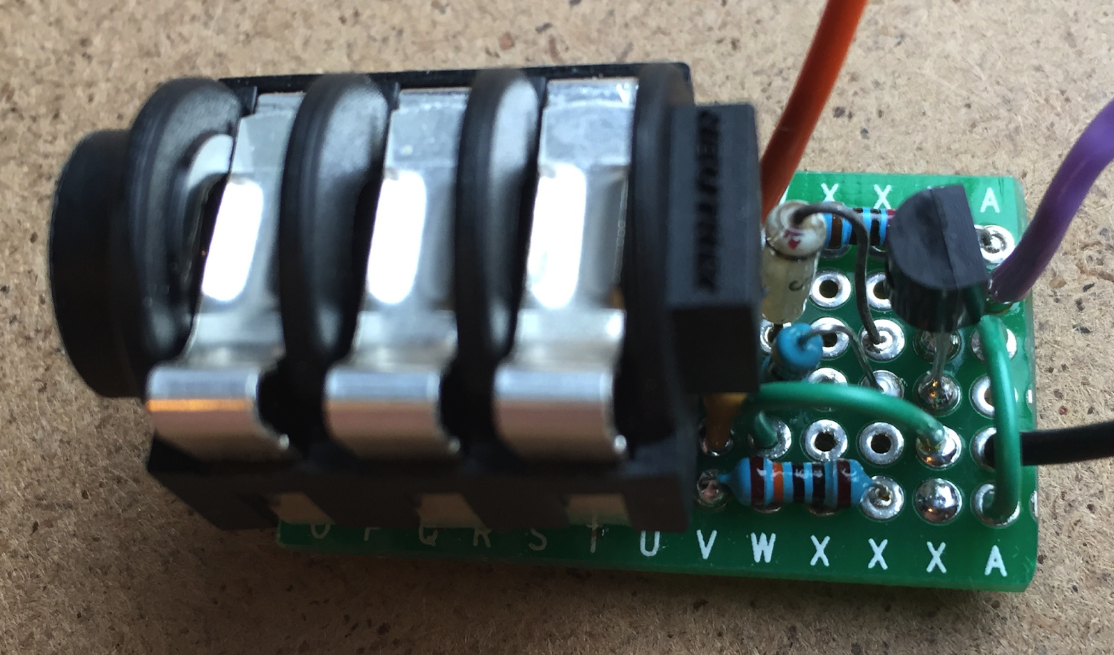
Then build the circuit on a piece of generic PCB mounted on the jack socket itself...


And then put it inside the pedal...


And connect the three output wires (shown on the right-hand side of the circuit diagram above) to the main digital board in the OWL (orange is 3.3 volts, black is ground, and purple is the PE2 connection):


Here's a diagram based on the Rebel Technology material:


And here's a view of the PCB with the pins marked again:


Finally, we put it all back together again:


...And there's now an extra socket, ready and waiting to be used for tap tempo and anything else that a patch programs it to do.

More information:

There's more background information, sketches, code and other material at my Github repository for this project. 

WARNING: 

As with any hardware project, you should only attempt this type of modification to an OWL pedal if you know what you are doing and are happy to carry out this sort of hardware hacking. I accept no responsibility for you messing up an OWL pedal. What you do with that pedal is up to you, and is your responsibility. 


Buy me a coffeeBuy me a coffee